- Minimum quantity should 1000 of "548 Through Hole Dip Transistor"
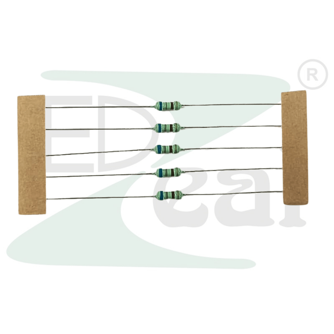
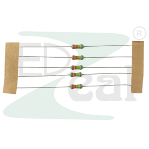
680 OHM± 5% 1/4W Through Hole Resistance
Resistance Value: 680 OHM
Power Rating: 1/4W
Material: Iron
Tolerance: ±5%
Packing Type: Tape Packing
(Excluding Tax)
680 OHM ±5% 1/4W Through Hole Resistor — CFR Carbon Film Axial (680R / 680E)
The 680 Ohm ±5% 1/4W Through Hole Resistor — widely identified as 680R or 680E in Indian electronics stores and PCB Bill of Materials documents — is a fundamental E12 and E24 series component that sits precisely between the 470 Ohm and 1K Ohm values. This positioning makes it the preferred choice when a 470 Ohm delivers slightly too much LED current, or when a 1K Ohm gives slightly too little — the 680 Ohm splits the difference cleanly and is trusted by engineers and makers across a wide range of current-limiting, biasing, filtering, and signal conditioning applications.
The 680 Ohm value is part of the E6, E12, and E24 standard resistor series, making it universally available and competitively priced — stocked by every component distributor worldwide. Electronics Pices Manufactured as a CFR (Carbon Film Resistor) on a ceramic substrate with axial leads and a flame-retardant lacquer body, this component delivers stable, low-noise, repeatable performance through both rapid breadboard prototyping and permanent soldered PCB assemblies.
Key Technical Specifications
Resistance Value: 680 Ohm (680Ω / 680R / 680E). Tolerance: ±5%. Power Rating: 1/4W (0.25 Watts). Type: CFR — Carbon Film Resistor, Through Hole (THT), Axial Lead. 4-Band Color Code: Blue – Grey – Brown – Gold. 5-Band Color Code: Blue – Grey – Black – Black – Gold. Maximum Operating Voltage: 350V. Operating Temperature Range: -55°C to +155°C. Temperature Coefficient: 0 / -850 ppm/°C. Lead Diameter: 0.55mm, copper-plated steel (24 AWG). Compliance: RoHS Compliant, Lead-Free.
What Does 680R and 680E Mean? — The Notation Explained
In Indian electronics stores, PCB BOMs, engineering datasheets, and component catalogs, you will regularly encounter three written forms of this component: 680 Ohm, 680R, and 680E. All three mean exactly the same resistor. The letters “R” and “E” are both IEC 60062 and BS 1852 standard substitutions for the Ohm symbol (Ω), used because the special character Ω cannot always be printed on physical component reels, plain-text BOM files, or legacy CAD design systems.
Whether your PCB BOM lists 680E, your supplier catalog shows 680R, or your instructor refers to it as “six-eighty Ohm” — you are always ordering the same 680Ω carbon film through-hole resistor. Recognizing this notation equivalence is an essential practical skill when working with Indian component suppliers and reading industry-standard PCB documentation.
Color Code — Fully Decoded for 4-Band and 5-Band
The 4-band color code for the 680 Ohm ±5% resistor is Blue – Grey – Brown – Gold. Blue represents the first significant digit: 6. Grey represents the second significant digit: 8. Together they form the base number 68. The Brown multiplier band represents ×10. Multiplying 68 by 10 gives exactly 680 Ohms. The Gold tolerance band confirms ±5% accuracy. Amazon
This means any individual unit will measure between 646 Ohms and 714 Ohms — fully within specification for all LED limiting, GPIO protection, transistor biasing, voltage division, and general-purpose analog and digital circuit applications.
The 5-band version consists of Blue – Grey – Black – Black – Gold, where the third Black band adds a third significant digit of 0, the fourth Black band is the ×1 multiplier, and Gold indicates ±5% tolerance. Electronics Pices Both color code versions resolve to the same nominal 680Ω value.
A practical identification note: the Blue and Grey color bands of the 680 Ohm resistor are distinctive and rarely confused once you have handled them a few times. Blue (6) has a strong cobalt tone, while Grey (8) appears as a neutral silvery-grey — together they form a recognizable pair that distinguishes this resistor clearly from the Yellow-Violet (470 Ohm) and Brown-Black (10–100 Ohm) combinations commonly stored in the same component tray.
Applications — Where the 680 Ohm Resistor Delivers Every Day
The 680 Ohm resistor is commonly used for LED current limiting. With a 5V supply and a typical red LED (2V forward voltage), the current is approximately 4–5mA, which provides visible illumination while extending LED lifespan. With a 12V supply and a red LED, approximately 15mA flows — well within the safe operating range for most standard LEDs. Electronics Pices
Microcontrollers often require inputs to be held at a defined logic state (high or low) when no external signal is present — the 680 Ohm resistor functions effectively as a pull-up or pull-down resistor in these configurations. Electronics Pices
Full list of proven, real-world applications in the Indian electronics market: LED current limiting for conservative, long-life brightness in 5V and 12V circuits, Arduino Uno, Nano and Mega GPIO output pin protection, Raspberry Pi and ESP32 indicator LED series resistors, push button pull-up and pull-down resistor networks, NPN and PNP transistor (BC547, BC548, 2N2222, S8050) base current-limiting resistors, NE555 timer oscillator and monostable circuit timing elements, RC low-pass and high-pass filter networks for audio and sensor signal conditioning, voltage divider circuits for scaling analog sensor outputs to ADC input ranges, I²C and SPI bus line pull-up resistors, UART serial communication line termination, motor driver signal protection resistors, audio signal attenuation and preamplifier input impedance setting, LDR and NTC thermistor voltage divider sensor interface circuits, and general-purpose breadboard and perf-board prototyping across all skill levels.
680 Ohm vs 470 Ohm vs 1K — LED Circuit Comparison
This is one of the most searched practical questions for Arduino and Raspberry Pi beginners in India. Here is the definitive answer for a 5V supply with a red LED (2V forward voltage):
A 470 Ohm resistor gives approximately 6.4mA — medium brightness, strong visual indication. A 680 Ohm resistor gives approximately 4.4mA — soft, professional-grade indicator brightness, ideal for dashboards and status panels. A 1K Ohm resistor gives approximately 3mA — dim, low-power beacon brightness. All three are safe for the LED — the 680 Ohm is the professional’s choice when a subtle, long-life indicator LED is the design goal. For maximum brightness in a demo or tutorial, the 220 Ohm or 330 Ohm is preferred.
Why CFR Carbon Film Is the Right Build
Carbon film resistors are the workhorse of general-purpose electronics — inexpensive, widely available, and suitable for non-critical applications like LED limiting or pull-up/pull-down networks with a typical tolerance of ±5%. Electronics Pices The helical carbon film groove cut into the ceramic rod base ensures tight resistance accuracy, stable temperature performance, and consistent value throughout the operating lifespan.
The axial through-hole construction delivers strong mechanical stability on both solderless breadboards and permanently soldered PCBs. The 0.55mm diameter leads are constructed of tin and copper plated over steel wire, allowing them to stand well with repeated insertions into solderless breadboards ProtoSupplies without bending, fatigue, or poor contact formation. The flame-retardant lacquer outer coating meets global safety standards — particularly important in enclosed PCB assemblies and consumer electronics where component heating must be managed within a product casing.
Safe Operating Guidelines
While rated at 0.25W (1/4W), industry best practice for continuous-duty circuits is to derate to 50–70% of rated wattage — keeping actual dissipation at or below 0.125W–0.175W during sustained operation. This extends the component’s operating lifespan and prevents resistance drift under prolonged thermal stress.
For the most common 680 Ohm application — LED limiting at approximately 4–5mA — actual power dissipation is approximately (4.5mA)² × 680Ω ≈ 0.014W, which is only 5.5% of the rated 0.25W limit. This resistor runs exceptionally cool in all standard LED and GPIO applications. Maximum safe continuous current at the 0.25W limit: I = √(P/R) = √(0.25/680) ≈ 19.2mA — providing ample safety headroom for every typical use case.
Frequently Asked Questions — Answered
What is the color code of a 680 Ohm resistor? 4-band: Blue, Grey, Brown, Gold. 5-band: Blue, Grey, Black, Black, Gold. Both indicate 680 Ohms with ±5% tolerance.
What does 680R and 680E mean? Both are IEC-standard notations where “R” and “E” substitute the Ohm symbol (Ω). 680R = 680E = 680 Ohm — the same component, three different labels used interchangeably by Indian stores and PCB BOM documents.
What is a 680 Ohm resistor used for? Primary uses: LED current limiting (soft, long-life indicator brightness), Arduino and Raspberry Pi GPIO pin protection, transistor base biasing (BC547, BC548), NE555 timer circuits, pull-up/pull-down networks, and RC filter design.
What current does a 680 Ohm resistor allow at 5V with an LED? With a red LED (2V forward voltage): I = (5V – 2V) / 680Ω ≈ 4.4mA. This delivers soft, professional-grade indicator brightness and maximizes LED operational lifespan.
Should I use 470 Ohm or 680 Ohm for my Arduino LED? Use 470 Ohm for medium-bright indication. Use 680 Ohm for softer, lower-power, longer-life indicator LEDs. Both are fully safe for the Arduino GPIO pin and the LED.
Is this resistor compatible with solderless breadboards? Yes — the 0.55mm axial leads are optimized for clean, firm, and reliable repeated insertion into standard 2.54mm pitch breadboard contacts without bending or contact failure.
Is this RoHS and lead-free compliant? Yes — fully RoHS compliant and manufactured lead-free.
Based on 0 reviews
Be the first to review “680 OHM± 5% 1/4W Through Hole Resistance”
Related products
-
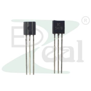
Through Hole (DIP) Transistor, DVAN
406 PCR Through Hole Dip Transistor
Specification:
- Type: Triac (Bidirectional Triode for Alternating Current)
- Package Type: TO-220 (through-hole)
- Repetitive Peak Off-State Voltage : 400V (maximum)
- RMS On-State Current : 4A (maximum)
- Gate Trigger Current : 5mA (typical)
- Gate Trigger Voltage : 1.3V (typical)
- Holding Current : 5mA (minimum)
- Power Dissipation : 1W (maximum)
- Operating Temperature: -40°C to +125°C
SKU: n/a -
Through Hole (DIP) Transistor, DVAN
457 Through Hole Dip Transistor
Specification:
- Type: NPN Bipolar Junction Transistor (BJT)
- Package Type: TO-92 (through-hole)
- Collector-Emitter Voltage : 45V (maximum)
- Collector Current : 100mA (maximum)
- Emitter-Base Voltage : 5V (maximum)
- DC Current Gain : 110 to 800 (depending on the variant)
- Transition Frequency : 250MHz (typical)
- Power Dissipation : 500mW (maximum)
- Operating Temperature: -55°C to +150°C
SKU: n/a -
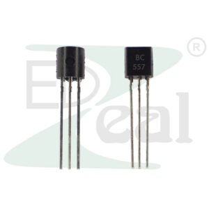
Through Hole (DIP) Transistor, DVAN
557 Through Hole Dip Transistor
Specification:
- Type: PNP Bipolar Junction Transistor (BJT)
- Package Type: TO-92 (through-hole)
- Collector-Emitter Voltage : 45V (maximum)
- Collector Current : 100mA (maximum)
- Emitter-Base Voltage : 5V (maximum)
- DC Current Gain : 110 to 800 (depending on the variant)
- Transition Frequency : 250MHz (typical)
- Power Dissipation : 500mW (maximum)
- Operating Temperature: -55°C to +150°C
SKU: n/a


There are no reviews yet.