
220 OHM± 5% 1/4W Through Hole Resistance
Resistance Value: 220 OHM
Power Rating: 1/4W
Material: Iron
Tolerance: ±5%
Packing Type: Tape Packing
(Excluding Tax)
220E OHM ±5% 1/4W Through Hole Resistor — CFR Carbon Film Axial (220R / 220 Ohm)
The 220E Ohm ±5% 1/4W Through Hole Resistor — also commonly identified as 220R or simply 220 Ohm — is one of the most widely stocked, most frequently used resistor values in electronics worldwide. It sits at the perfect operational sweet spot: providing exactly the right amount of current limiting for LED circuits on 3.3V and 5V systems, reliable GPIO pin protection on Arduino and Raspberry Pi boards, and robust transistor base biasing in small-signal switching applications.
Manufactured as a CFR (Carbon Film Resistor) on a ceramic rod base with a flame-retardant lacquer coating and axial through-hole leads, this component delivers consistent, stable, low-noise performance across both rapid prototyping environments and permanent PCB assemblies.
Whether you are building your first Arduino LED circuit as a student, populating a professional PCB as an engineer, or stocking a components tray for a makerspace — this is the one resistor you will always reach for first.
Key Technical Specifications
Resistance Value: 220E Ohm (220Ω / 220R / 220 Ohms). Tolerance: ±5%. Power Rating: 1/4W (0.25 Watts). Type: CFR — Carbon Film Resistor, Through Hole (THT), Axial Lead. 4-Band Color Code: Red – Red – Brown – Gold. 5-Band Color Code: Red – Red – Black – Black – Gold. Maximum Operating Voltage: 350V. Operating Temperature Range: -55°C to +155°C. Temperature Coefficient: 0 / -850 ppm/°C. Lead Type: Copper-plated steel, 0.55mm diameter (24 AWG). Compliance: RoHS Compliant, Lead-Free.
What Does “220E” Mean? — The Notation Explained
The “E” in 220E is an IEC 60062 and BS 1852 standard component labeling notation where the letter “E” represents the Ohm symbol (Ω). This notation is widely used in Indian electronics component stores, PCB BOMs (Bill of Materials), and engineering datasheets because it avoids printing special symbols (Ω) on physical component labels and in plain-text documents.
So 220E = 220R = 220 Ohms = 220Ω — all four notations refer to the exact same component. Understanding this is essential when reading Indian PCB BOMs and component supplier catalogs where all three variants may appear interchangeably.
Color Code — Fully Decoded for 4-Band and 5-Band
The standard 4-band color code for the 220E Ohm ±5% resistor is: Red – Red – Brown – Gold.
Reading left to right — the first Red represents digit 1 = 2. The second Red represents digit 2 = 2. Together they form the significant base number 22. The Brown band is the multiplier, representing ×10. Multiplying 22 by 10 = 220 Ohms exactly. The Gold tolerance band at the end confirms ±5% accuracy.
This means any individual unit will measure between 209 Ohms and 231 Ohms — well within acceptable range for LED current limiting, GPIO protection, voltage dividers, and all general-purpose analog and digital circuit applications.
For 5-band versions: Red – Red – Black – Black – Gold, where the third Black band adds a third significant digit of 0, the fourth Black band is the ×1 multiplier, and Gold remains the ±5% tolerance band. Both color code versions resolve to the same nominal 220 Ohm value.
Applications — Where the 220E Resistor Is Used Every Day
The 220E / 220R value is the single most recommended current-limiting resistor for LEDs running on 3.3V and 5V supply rails — the two dominant voltages in Arduino UNO, Arduino Nano, Raspberry Pi, ESP32, ESP8266, and STM32 development systems. At 5V with a standard red or green LED (forward voltage approximately 2.0V–2.2V), a 220E series resistor delivers approximately 12–14 mA of LED current — bright, fully safe, and well within the 20mA absolute maximum rating of virtually all standard 3mm and 5mm LEDs.
Proven, high-frequency applications in the Indian electronics market include: LED current limiting in 3.3V and 5V microcontroller circuits, Arduino Uno and Nano GPIO digital output pin protection, Raspberry Pi GPIO pin series protection, ESP32 and ESP8266 indicator LED circuits, push button input pull-up and pull-down resistor networks, transistor (BC547, BC548, 2N2222) base current limiting in switching circuits, NE555 timer-based oscillator and monostable timing configurations, RC filter circuits for signal smoothing and noise rejection, signal line series termination for ringing suppression in high-speed digital PCB traces, voltage divider circuits for analog input signal conditioning, perf-board and solderless breadboard prototyping across all skill levels, and status indicator LED networks in consumer electronics and industrial sensor PCBs.
CFR — What Makes Carbon Film Resistors the Right Choice
CFR (Carbon Film Resistor) technology involves coating a homogeneous layer of pure carbon film onto a high-grade ceramic rod base. A precision helical groove is then cut into the resistive layer to achieve the exact resistance value. Tinned copper leads are welded to end caps, and the entire assembly is coated with a flame-retardant tan lacquer for protection and identification.
Compared to older carbon composition resistors, CFR types produce significantly lower electrical noise — a measurable advantage in audio circuits, precision analog signal chains, and sensor interfaces where noise floor directly affects circuit performance. The axial lead through-hole construction provides strong mechanical stability during both manual hand soldering and automated wave soldering, with the 0.55mm copper-plated steel leads designed specifically for clean, repeatable insertion into solderless breadboards without bending, loosening, or creating poor contact — a common frustration with cheaper thin-lead alternatives. The flame-retardant coating meets global safety standards and is particularly relevant in enclosed PCB assemblies and consumer electronics where component heating must be managed within the product casing.
Safe Operating Guidelines — How to Use This Resistor Correctly
The rated power of 0.25W (1/4W) represents the absolute maximum continuous dissipation. Industry best practice for continuous-duty circuits is to derate to 50–70% of rated wattage — ideally keeping actual dissipation at or below 0.125W to 0.175W. This extends operating lifespan significantly and prevents resistance drift under prolonged thermal stress.
For the most common 220E application — LED current limiting at 12–14mA — actual power dissipation is approximately (14mA)² × 220Ω ≈ 0.043W, which is only 17% of the rated 0.25W limit. This component runs cool in LED circuits and will comfortably outlast every other component in your circuit under normal operating conditions.
Maximum theoretical current at the 0.25W power limit: I = √(P/R) = √(0.25/220) ≈ 33.7mA. In all practical LED and GPIO protection applications, actual current stays well below this threshold.
Frequently Asked Questions — Answered
What does 220E mean on a resistor? The “E” is an IEC 60062 notation for Ohms, used in Indian component stores and PCB BOMs. 220E = 220R = 220 Ohm = 220Ω — all the same component.
What is the color code of a 220E resistor? 4-band: Red, Red, Brown, Gold. 5-band: Red, Red, Black, Black, Gold. Both indicate 220 Ohms with ±5% tolerance.
Is 220E the right resistor for Arduino LED circuits? Yes — the 220E (220 Ohm) resistor is the most widely recommended current-limiting value for standard 5mm and 3mm LEDs powered from Arduino 5V or 3.3V output pins. It is found in virtually every beginner electronics kit sold in India.
What is the difference between 220E, 220R, and 220 Ohm? None — they are three different written notations for the exact same 220 Ohm resistance value. “E” and “R” are both IEC-standard substitutes for the Ω symbol.
What current does a 220E resistor allow at 5V with an LED? Using Ohm’s Law with a 2V LED forward voltage: I = (5V – 2V) / 220Ω = 3/220 ≈ 13.6mA — ideal for safe, bright LED operation on any Arduino, ESP32, or Raspberry Pi board.
Is this resistor RoHS and lead-free compliant? Yes — fully RoHS compliant and manufactured lead-free.
Can this resistor be used on a breadboard? Yes — the 0.55mm axial leads are optimized for clean, reliable, repeated insertion into standard 2.54mm pitch solderless breadboards without bending or contact failure.
Based on 0 reviews
Be the first to review “220 OHM± 5% 1/4W Through Hole Resistance”
Related products
-
Through Hole (DIP) Transistor, DVAN
136 BT Through Hole Dip Transistor
Specification:
- Type: Triac (Bidirectional Triode for Alternating Current)
- Package Type: TO-220 (through-hole)
- Repetitive Peak Off-State Voltage : 600V (maximum)
- RMS On-State Current : 4A (maximum)
- Gate Trigger Current : 5mA (typical)
- Gate Trigger Voltage : 1.3V (typical)
- Holding Current: 5mA (minimum)
- Power Dissipation : 1W (maximum)
- Operating Temperature: -40°C to +125°C
SKU: n/a -
Through Hole (DIP) Transistor, DVAN
431 TL Through Hole Dip Transistor
Specification:
- Type: Adjustable Shunt Regulator
- Package Type: Through-hole
- Anode Voltage : 36V (maximum)
- Cathode Voltage : 36V (maximum)
- Output Current : 1mA to 100mA (typical)
- Dynamic Impedance: 0.22Ω (typical)
- Operating Temperature: -40°C to +125°C
SKU: n/a -
Through Hole (DIP) Transistor, DVAN
548 Through Hole Dip Transistor
Specification:
- Type: NPN Bipolar Junction Transistor (BJT)
- Package Type: TO-92 (through-hole)
- Collector-Emitter Voltage : 30V (maximum)
- Collector Current : 100mA (maximum)
- Emitter-Base Voltage : 5V (maximum)
- DC Current Gain : 110 to 800 (depending on the variant)
- Transition Frequency : 250MHz (typical)
- Power Dissipation : 500mW (maximum)
- Operating Temperature: -55°C to +150°C
SKU: n/a -
Through Hole (DIP) Transistor, DVAN
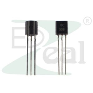
558 Through Hole Dip Transistor
Specification:
- Type: PNP Bipolar Junction Transistor (BJT)
- Package Type: TO-92 (through-hole)
- Collector-Emitter Voltage : 40V (maximum)
- Collector Current : 100mA (maximum)
- Emitter-Base Voltage : 5V (maximum)
- DC Current Gain : 110 to 800 (depending on the variant)
- Transition Frequency : 250MHz (typical)
- Power Dissipation : 500mW (maximum)
- Operating Temperature: -55°C to +150°C
SKU: n/a -
Through Hole (DIP) Transistor, DVAN
406 PCR Through Hole Dip Transistor
Specification:
- Type: Triac (Bidirectional Triode for Alternating Current)
- Package Type: TO-220 (through-hole)
- Repetitive Peak Off-State Voltage : 400V (maximum)
- RMS On-State Current : 4A (maximum)
- Gate Trigger Current : 5mA (typical)
- Gate Trigger Voltage : 1.3V (typical)
- Holding Current : 5mA (minimum)
- Power Dissipation : 1W (maximum)
- Operating Temperature: -40°C to +125°C
SKU: n/a


There are no reviews yet.